FatBoy upscale to D/E engine mount & my first Kevlar shock mount
From the 2005 Estes catalog (the last year it was sold):


When thinking about all the old kits on my shelf, trying to decide what to build next, I remembered reading lots of notes on RocketReviews about converting the Estes FatBoy to use D or E engines. The kit comes with through the wall balsa fins that anchor the fins with the engine mount. I’ll try to leverage this and use a larger launch lug (3/16”) to stabilize liftoff with a more powerful engine. I can just use the BT-80 card stock centering rings that came in the Estes D & E mount kit (#3159) glued together for double thickness, instead of trying to cut basswood centering rings. I'll use a 4” Apogee E engine hook (#24049). I'll need to check if there's enough space for chute & wadding w/ longer engine mount. If not, I may need to build a baffle.
I call it DE’ FatBoy or “De’ FatBoy”
OpenRocket predicts a 24 mm mount DE’ FatBoy will fly:
416’ on C11-5
847’ on D12-5
1297’ on E9-6
Some RocketReviews cautioned about checking the Center of Gravity (CG) when planning to use larger engines like the E9, because the larger and longer engine mount puts more weight in the back of the rocket, and I may need weight in nose cone (see Vern Estes' article about rocket stability and Tim Van Milligan's more recent Peak of Flight article).
I started by cutting two sets of BT-80 (2.6”) centering rings from my Estes D/E mount kit . I glued each pair together with Titebond, dull side to dull side, and left them to dry overnight under a water bottle, with the two pairs separated by wax paper.

I measured the space between the nose cone and engine block to ensure longer engine mount leaves room for parachute & wadding. It looks like ~2 1/2”, so should be okay.

Some Kevlar shock cord I'd ordered from Amazon arrived today so I installed an anti-zipper arrangement per the Peak of Flight newsletter #282 (March 15, 2011).


This should help keep the shock cord straight and minimize the risk of the Kevlar cutting the body tube upon parachute deployment.

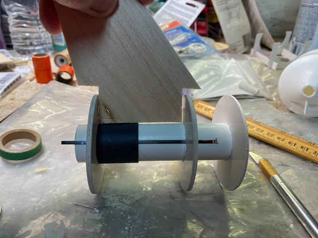
Next I glued the engine mount into the body by first test fitting it and measuring where the upper centering ring would be then spreading glue below that position. After sliding the engine mount part of the way in, I applied glue through the fin slots to the top of the second engine ring, then pushed the engine mount to its final position, slowly turning the assembly so the extra glue would take position on the outer edge of the second ring. Next I applied glue to the top of the engine mount, allowing it to dry upright before applying glue around the bottom engine mount. After the engine mount was in place, I used my Estes fin alignment guide to position all three fins in the body with glue. I had to trim a couple of millimeters off each fin’s root surface then sand that edge so the fins would be flush with the body tube, because I’d used the wider engine mount. When mounting the fin alignment guide I had to use spacers (a D engine spacer) to lift the body off the surface of the alignment guide because of the backward sweep of the fins.

The next day I painted Elmers wood filler mixed with water on the surface of the fins and filled the spiral on the body tube with wood filler.

Before applying the wood filler, I stuffed the unassembled parachute and shock cord into the body along with the nose cone to test where the balance point is, i.e., the center of gravity (CG). Adding an E engine and testing the center of gravity again showed that the CG had moved back to approximately 3/4 of an inch above the fins (pencil marks on the body tube, above). OpenRocket simulations with five centering rings and a 4” engine mount confirmed that the center of gravity (CG) was moved back and might even be behind the Center of Pressure (CP), showing that I need to add weight in the nose cone to keep the Rockets stable with larger engines. OpenRocket says my rocket should weigh 4.65 oz empty; my un-sanded and un-painted empty weight w/ parachute & shock cord is 4.0 oz, and that the CG empty was at 6.1 in and the CP at 8.0 in for a stability of 0.739 cal. With an E9 the CG moves to 7.4 in with a stability of 0.235 cal. Simulation shows adding four 0.25 oz blocks of Estes clay should stabilize the DE’ FatBoy even when launching with an E9 engine to a CG of 6.9 in and a stability of 0.403 cal; a D12 engine gives a CG of 6.7 in with a stability of 0.503 cal (CG empty = 5.6 in with a stability of 0.932 cal). The diagram below shows the CG (blue symbol) almost on top of the CP (red symbol) with an E9 engine and no additional weight.


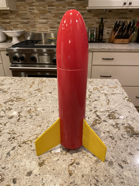
I’ve attached the 3/8” launch lug and assembled the 18” parachute. The rocket has been sanded and primed. The next steps are to sand the primer with 330 paper then paint. I’m planning on using Rust-oleum Sunburst Yellow for the fins and Rust-Oleum Carnival Red for the body and nose cone then will decide whether to put decals on the fins and/or body. I found a spare set of fin decals so may go all out on the decorations. I’m planing on launching this at a local club launch in a couple of weeks, weather permitting. Here's a preview of what I'm hoping it will look like (generated by OpenRocket):

To summarize the changes I made from the original Estes kit:
- Replaced the 2.75” 18 mm engine mount with a 4” 24 mm engine mount and a 4” engine clip
- Reinforced the engine mount centering rings, so two are double thickness
- Added a third centering ring at the top of the engine mount
- Prepared an anti-zipper Kevlar shock mount for the parachute and shock cord
- Used a larger launch lug
- Glued lead fishing sinkers totaling 1.25 oz in the nose cone using 5 minute epoxy for increased stability
The final flight projections from OpenRocket (with 4 X 0.25 oz with 1.25 oz nose cone weight added):
C11-5 has apogee at 238 feet with parachute ejection at 40.9 ft/sec
D12-5 has apogee at 604 feet with parachute ejection at 10.1 ft/sec
E9-6 has apogee at 1012 feet with parachute ejection at 31.8 ft/sec
Not bad for a kit that was only designed to fly a maximum of 325 feet!

The original Estes FatBoy plans show to use 5 squares of flame retardant wadding to protect the parachute; that page is missing from the plans available online.
UPDATE:
I finished my DE' FatBoy in time for my first club launch. I painted the fins with Rust-Oleum Sunburst Yellow gloss enamel spray paint, taping off the body, waited eight or nine hours for it to dry then covered the fins with green Frog Tape and painted the body with Rust-Oleum Carnival Red gloss enamel spray paint. I'm really pleased it turned out almost as simulated above (minus the fake flames):


Comments
Post a Comment